Specifying the wrong hydraulic control valve type costs facilities thousands in wasted productivity, premature component failure, and inefficient operation. Equipment runs sluggishly because directional valve was selected without adequate flow capacity. Manufacturing lines experience erratic operation when pressure control valves can’t respond fast enough to load changes. Mobile equipment burns excessive fuel because flow control valves force systems to work harder than necessary.
The hydraulic control valve market offers hundreds of variations serving different control functions, pressure ratings, and response characteristics. This variety exists because no single valve type optimally serves all applications. Understanding which control valve types match specific operational requirements separates systems that perform reliably from those plagued by constant adjustment and premature replacement.
This examination focuses on practical valve selection based on control functions, operating requirements, and application contexts. By understanding how different hydraulic control valve designs achieve specific control objectives, equipment designers and maintenance professionals can specify appropriate components that deliver required performance without unnecessary complexity or cost.
Understanding Hydraulic Control Valve Functions
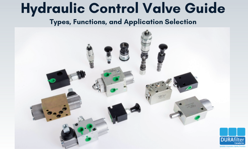
Hydraulic control valves regulate three fundamental parameters: direction, pressure, and flow. Each valve category addresses specific control needs, with designs optimized for particular operating conditions and performance requirements.
- Directional Control Valves
- Directional control valves determine fluid path through hydraulic circuits, enabling actuator movement and function selection. These valves represent the most visible hydraulic control valve type in mobile and industrial equipment, translating operator inputs into mechanical actions.
- Spool-type directional valves dominate modern hydraulic systems through their reliable operation and flexible configuration options. Precision-machined spools sliding within valve bodies open and close internal passages directing fluid to different ports. The spool position determines which actuators receive pressure and which connect to return, enabling complex multi-function control through single valve assemblies.
- Poppet-type directional valves use spring-loaded elements that seat against ports, providing positive sealing with minimal internal leakage. These valves excel in applications requiring tight shutoff or where contamination makes spool-type valves impractical. The design trades some flow capacity for improved sealing performance.
Position options in directional control valves range from simple 2-position designs to complex 3-position configurations with various center conditions. Closed-center designs block all ports in neutral, while open-center configurations allow continuous pump flow. Tandem-center and float-center options address specific circuit requirements balancing efficiency against control characteristics.
Actuation methods include manual levers, mechanical cams, pilot pressure, solenoid operation, and proportional electronic control. Selection depends on whether human operators control functions directly or automation systems require remote valve operation.
- Pressure Control Valves
- Pressure control valves limit maximum system pressure, reduce pressure in branch circuits, or enable pressure-sequenced operation. These control valve types protect components while optimizing performance across varying load conditions.
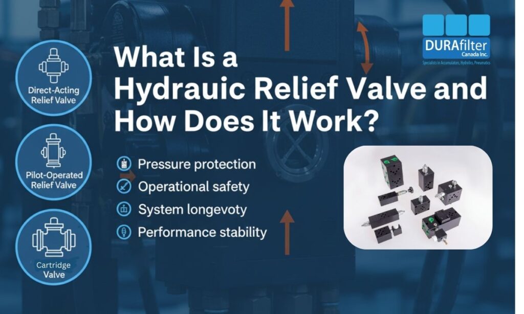
- Relief valves represent the most common pressure control application, limiting maximum system pressure by opening bypass paths when pressure exceeds setpoints. Direct-acting designs respond to spring force balanced against hydraulic pressure, while pilot-operated configurations use small pilot stages controlling larger main stages for better pressure regulation and higher flow capacity.
- Pressure reducing valves maintain constant reduced pressure in branch circuits regardless of inlet pressure variations. These valves enable multiple pressure levels within single hydraulic systems, protecting sensitive components while allowing high-pressure circuits to serve demanding functions.
- Sequence valves enable pressure-controlled operation sequences where one function must complete before another begins. These valves remain closed until inlet pressure reaches setpoint, then open allowing flow to secondary circuits. Applications include clamping operations requiring workpiece securing before machining begins, or multi-stage lifting where stabilization must occur before load transfer.
- Unloading valves dump pump flow to tank at low pressure when systems don’t require full pressure, reducing power consumption and heat generation. These valves respond to pilot signals indicating whether working pressure is needed, automatically shifting between high-flow/low-pressure and low-flow/high-pressure operation modes.
- Flow Control Valves
- Flow control valves regulate fluid velocity through circuits, controlling actuator speed and system timing. These hydraulic control valves enable precise motion control and optimize performance across varying operating conditions.
- Throttle valves provide simple flow restriction through adjustable orifices, though flow varies with pressure differential across the valve. These basic designs suit applications where speed consistency isn’t critical or where pressure remains relatively constant.
- Pressure-compensated flow control valves maintain constant flow regardless of pressure variations by automatically adjusting orifice size to compensate for changing pressure differentials. These designs deliver consistent actuator speeds despite varying loads, improving machine performance and productivity.
- Temperature-compensated flow control maintains flow consistency across temperature ranges by compensating for viscosity changes affecting flow through fixed orifices. This refinement becomes important when equipment operates across wide temperature ranges where viscosity variations would otherwise cause speed inconsistencies.
- Priority flow dividers ensure critical functions receive required flow before directing remaining capacity to secondary circuits. These valves maintain steering response in mobile equipment regardless of implement demands, or guarantee essential machine functions operate properly even when auxiliary functions consume significant flow.
Choosing the Right Control Valve Type for Your Application
Appropriate valve selection requires understanding operational requirements beyond basic function categories. Application context, duty cycle, contamination exposure, and performance expectations all influence which hydraulic control valve designs deliver optimal results.
Industrial Manufacturing Equipment
Manufacturing systems require reliable valve performance in relatively clean, temperature-controlled environments. These applications often demand precise control and consistent operation across extended production runs.
Spool-type directional valves with solenoid actuation dominate automated manufacturing equipment, providing reliable switching with integration into electronic control systems. Proportional valves enable variable control supporting precision positioning in assembly operations, material handling, and processing equipment.
Pressure control in manufacturing typically uses pilot-operated relief valves providing accurate pressure regulation at flow capacities matching production equipment demands. Filter elements maintain the fluid cleanliness these sensitive valves require for reliable operation.
Flow control valves in manufacturing equipment regulate cycle times and synchronize multiple actuators. Pressure-compensated designs ensure consistent operation despite varying loads throughout production cycles.
Mobile Construction Equipment
Construction machinery faces demanding conditions including vibration, contamination, temperature extremes, and operator-induced shock loads. Control valve selection must account for these harsh realities while delivering reliable performance.
Directional control valves in construction equipment typically use robust spool designs with pilot operation reducing effort required for manual control. Load-sensing systems adjust pump output matching flow demands, improving fuel efficiency while maintaining responsive control.
Pressure control in mobile equipment protects components from shock loads and prevents excessive pressures during stalled conditions. Main relief valves set maximum system pressure while individual function relief valves protect specific circuits from overload.
Flow control in construction equipment divides available pump capacity among multiple simultaneous functions. Proportional control increasingly appears in modern equipment, enabling smoother operation and improved fuel efficiency.
Oil and Gas Operations
Energy industry equipment operates under extreme conditions requiring absolute reliability. Hydraulic control valves for drilling, production, and processing equipment must withstand high pressures, contamination, and demanding duty cycles.
Explosion-proof directional control valves meeting safety certifications enable safe operation in hazardous atmospheres. These specialized designs prevent ignition sources while maintaining hydraulic control functionality in potentially explosive environments.
High-pressure applications in oil and gas operations require control valves rated for extreme service conditions. Pressure control becomes particularly important protecting expensive components and ensuring safe operation. Relief valves must handle full pump flow at maximum pressure without damage.
Flow control in oilfield equipment regulates operational speeds and divides hydraulic power among multiple functions on drilling rigs and production equipment.
Automotive Manufacturing Facilities
Automotive assembly operations use hydraulic control valves throughout robotic systems, material handling equipment, and assembly line machinery. These applications demand reliability, precision, and integration with automated control systems.
Proportional directional valves enable precise control of robotic welding equipment, material positioning systems, and assembly operations. Electronic control integration supports sophisticated automation while enabling diagnostic capabilities identifying performance variations before failures occur.
Pressure control in automotive manufacturing protects expensive tooling while ensuring consistent force application in pressing, forming, and assembly operations. Accurate pressure regulation directly impacts product quality and process reliability.
Flow control valves regulate cycle times throughout assembly processes, synchronizing operations and maintaining production throughput.
Key Factors to Consider When Selecting a Hydraulic Control Valve
Specifying appropriate hydraulic control valves requires considering factors beyond basic function categories. These additional parameters significantly impact performance, reliability, and total cost of ownership.
Flow Capacity Requirements
- Undersized valves create excessive pressure drops that reduce system efficiency while generating heat and reducing available pressure for productive work. Flow capacity must accommodate peak demands with margin for pressure drop remaining within acceptable limits.
- Valve pressure ratings must exceed maximum system pressure with appropriate safety factors. Operating valves near maximum ratings shortens service life and increases failure risk. Standard practice specifies valves rated at least 25% above maximum operating pressure.
- Response time requirements vary dramatically between applications. Rapid on-off control demands fast-acting solenoid valves, while some applications benefit from slower, controlled transitions reducing shock loads.
Contamination Resistance
- Spool valve sensitivity to contamination varies with internal clearances and spool geometry. Precision valves with tight clearances deliver excellent control characteristics but require cleaner fluid than robust designs with larger clearances tolerating contamination better.
- Poppet valves generally tolerate contamination better than spool designs, making them suitable for applications where filtration standards prove difficult maintaining.
- Filtration requirements vary based on valve sensitivity. Proportional and servo valves demand ISO cleanliness codes of 16/14/11 or better, while standard spool valves function adequately at 18/16/13.
Mounting and Integration
- Subplate mounting enables standardized valve installation with simplified plumbing and easy valve replacement. This approach dominates industrial applications where multiple valves concentrate in control manifolds.
- In-line mounting suits mobile applications where space efficiency and direct connection to actuators proves advantageous. These installations reduce plumbing complexity while enabling compact equipment packaging.
- Manifold integration consolidates multiple valve functions into single assemblies, reducing leak points while enabling sophisticated control circuits. Custom manifolds optimize flow paths and minimize pressure losses while supporting complex control requirements.
Control Valve Performance Optimization and Troubleshooting
Even properly selected hydraulic control valves require appropriate installation, adjustment, and maintenance delivering optimal performance throughout service life.
Installation Best Practices
- Proper orientation matters for some valve designs where gravity affects spool position or contamination settlement influences operation.
- Pilot pressure supply must meet requirements for pilot-operated valves functioning properly. Inadequate pilot pressure causes sluggish response or complete control failure. Verify pilot circuits provide sufficient flow and pressure before investigating valve problems.
- System flushing before valve installation prevents contamination from damaging new components. Construction debris, scale, and weld slag present in new systems damage valves immediately if allowed reaching sensitive control elements.
Common Valve Problems
- Sluggish operation usually indicates contamination affecting spool or poppet movement. Internal wear from contaminated fluid also increases clearances causing delayed response. Addressing fluid cleanliness and considering valve overhaul or replacement resolves these performance issues.
- Internal leakage from worn seals or damaged spool surfaces reduces control precision while generating heat. Monitoring control valve performance over time identifies gradual degradation suggesting maintenance needs before complete failure occurs.
- Stuck valves result from contamination, corrosion, or varnish deposits preventing movement. These failures often trace to inadequate filtration or fluid maintenance allowing deposits forming on internal surfaces. Professional repair services can restore valve performance when internal damage requires attention beyond field maintenance capabilities.
Maintenance Considerations
- Scheduled inspection during equipment maintenance intervals identifies developing valve problems before they impact operations. Checking for external leaks, verifying smooth operation, and confirming proper adjustment prevents unexpected failures.
- Fluid analysis programs detect contamination trends affecting valve life. Particle counts exceeding system cleanliness targets indicate filtration improvements needed protecting valves and other sensitive components.
- Performance documentation establishes baselines for comparison during subsequent inspections. Declining response times, increased leakage, or adjustment drift signal developing problems requiring attention.
Emerging Hydraulic Control Valve Technologies
- Proportional control continues replacing simple on-off valves in applications benefiting from variable control. Electronic integration enables sophisticated control algorithms optimizing performance while supporting diagnostic capabilities identifying problems before failures occur.
- Load-sensing systems adjust pump output matching instantaneous flow demands, dramatically improving energy efficiency compared to constant-flow systems. These systems require specialized control valves but deliver fuel savings justifying higher initial costs in many applications.
- Electrohydraulic integration brings precision servo control to applications previously limited to simpler valve types. Declining component costs and improving reliability expand electrohydraulic applications beyond traditional motion control to include mobile equipment and general industrial machinery.
How to Select the Best Hydraulic Control Valve
Successful hydraulic control valve specification requires understanding application requirements, operating conditions, and performance expectations. No single valve type optimally serves all applications, appropriate selection balances multiple factors delivering required control without unnecessary complexity.
- Manufacturer specifications provide essential guidance for valve selection in equipment design and replacement scenarios. Following OEM recommendations ensures compatibility while maintaining performance and warranty coverage.
- Application analysis identifies actual control requirements distinguishing between peak and typical demands. Right-sizing valves for realistic rather than theoretical maximum conditions optimizes performance and cost.
- System integration considers how control valves interact with pumps, actuators, and other components. Valve performance depends on proper system design and component compatibility beyond individual valve specifications.
Working with experienced hydraulic suppliers ensures access to technical expertise and quality components supporting reliable system performance. DuraFilter’s three decades serving hydraulic markets provides the knowledge and product selection helping customers specify appropriate control valves for demanding applications.
Understanding hydraulic control valve selection enables informed decisions matching control requirements to application realities. Proper valve specification delivers the performance and reliability hydraulic systems require without sacrificing efficiency or increasing unnecessary costs.
FAQ’s
Q. What Are the Most Common Hydraulic Control Valve Types?
Ans. The most common hydraulic control valve types are:
- Directional Control Valves: Control the direction of hydraulic fluid to start, stop, or change actuator movement
- Pressure Control Valves: Regulate system pressure to protect components and ensure safe operation
- Flow Control Valves: Control the speed of hydraulic actuators by regulating fluid flow
- Proportional Control Valves: Allow variable control of flow and pressure for precise movement
- Servo Control Valves: High-precision valves used in advanced automation and motion control systems
Selecting the right hydraulic control valve depends on application requirements such as pressure range, flow demand, response time, and operating environment.
Q. Can a Hydraulic Control Valve Be Repaired or Rebuilt?
Ans. Yes, many hydraulic control valves can be repaired or rebuilt if the valve body is not damaged. Common rebuilds include replacing seals, springs, and worn internal components. However, valves with severe scoring, corrosion, or structural damage should be replaced to ensure safe and reliable operation.
Q. Directional vs Proportional Control Valves: What’s the Difference?
Ans. Directional control valves operate in simple on/off positions to direct fluid flow, while proportional control valves allow variable control of flow or pressure based on electrical input. Proportional valves are used where smooth motion and precise control are required, whereas directional valves suit basic hydraulic functions.